Quick Change Tool Post
Update: I've since replaced this tool post with a newer, better design (albeit one that requires a milling machine to make. Read about it here.
As far as I can tell, this is a fairly standard QCTP design. My intention had been to build a QCTP that was very closely based on the one on Mike's Workshop, but I made it (along with one tool holder) and got frustrated by the operation of the post. I suspect this was a weakness in the way I'd made it, but I found that if I tightened it enough that I could take heavy cuts without the tool holder moving, it became extremely difficult to remove the tool holder. Therefore, I decided to use a simpler (and probably more conventional) approach: a slit in the tool holder and a clamping screw to close the hole up. The toolpost and all the tool holders except the tangential tool holder were made using only the lathe and drill.
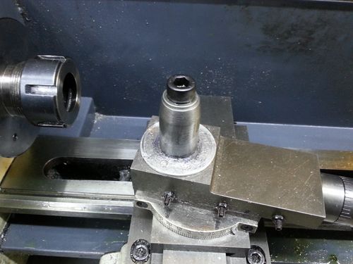
My toolpost is shown here:
It's a very simple design, basically consisting of a 24.9 mm cylinder. At it's simplest, that's all you need. I've added a slight taper on the top of the toolpost: this makes it marginally easier to get the tool holder onto the toolpost. I've also added a 1 mm thick aluminium disc underneath the toolpost. This is there simply to take any impact from the height-adjustment screws when the tool holder is fitted to the toolpost.
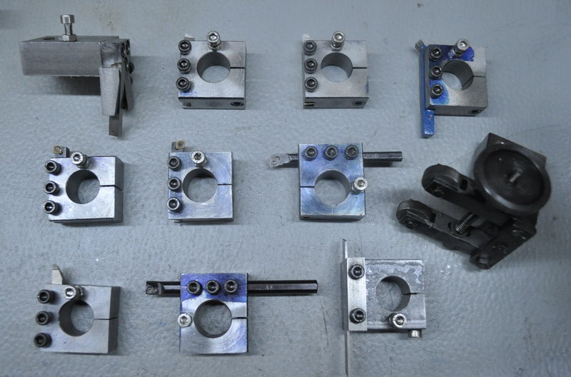
Here are some of the tool holders I've made so far:
From left-to-right and then top-to-bottom, these are: my tangential tool holder, a roughing tool, a fine finishing tool, a chamfering tool, a right-hand and left-hand carbide insert tool, a carbide insert boring bar, a knurling tool, an external 60° threading tool, an internal 60° carbide insert threading tool and a parting tool.
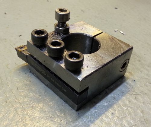
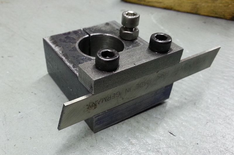
This is a simple right-hand turning tool. To make this tool, I started with a length of 25 mm × 50 mm mild steel. I cut a 50 mm length off and used the lathe's four jaw chuck to clean up the saw cuts. I then bored the 25 mm hole in the middle. After that, all the (5) screw holes were drilled and tapped and then I used the bandsaw to cut the slit. I then put a spacer on the toolpost and mounted the holder on the toolpost. A 10 mm end-mill was put in the lathe's chuck and this was used to cut the slot for the tool. The spacer's thickness was chosen such that the tool would be on centre height when the spacer was removed and the tool inserted. That was all there was to it.
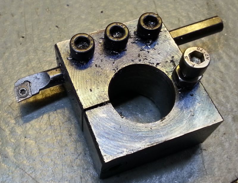
The boring tool holder was made in much the same way as the right-hand turning tool. The only difference was that the hole for the boring bar was drilled with the tool holder on the toolpost at the normal height rather than using a spacer.
The parting tool holder is a slightly unusual design in that the lowest part of the blade is mounted at centre height. The blade has a slight angle on the leading edge and it was necessary to re-grind this such that when the blade is inverted the leading point remains on the tailstock side. The advantage of this design is that parting can be done with the lathe running backwards, which seems to significantly reduce the instances of the blade digging in. This and the angular contact bearings I fitted to the headstock have made parting vastly more enjoyable than it had been previously.
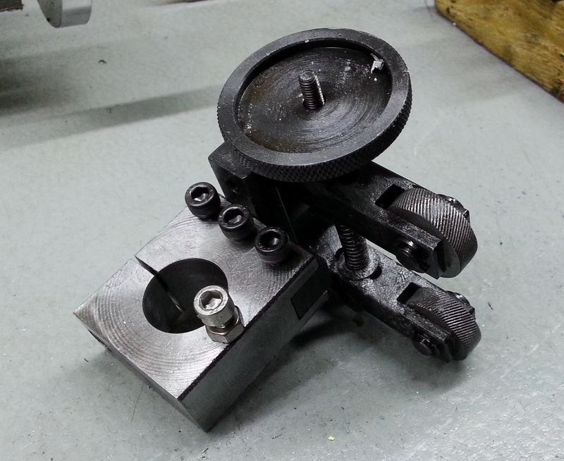
This is a simple knurling tool holder. It is similar to the other simple holders but has a 13 mm slot milled in the side to hold the (off-the-shelf) knurling clamp.
This website is free and ad-free, but costs me money to run. If you'd like to support this site, please consider making a small donation or sending me a message to let me know what you liked or found useful.

