Travel Tool Chest & Workbench Build Process
Page 29 of 144
Posted 10th March 2023
The next job was to start working on the (ten) mortice and tenon joints that make up the back pieces:
I used blind mortice-and-tenon joints on my side table, but the tenons were cut on the table saw and the blind mortices were a lot more forgiving than the through (and probably wedged) ones I'm going to use here.
I had a few practices on some bits of scrap. Most of them looked awful but one looked okay-ish, so I'm going to use the method that I used on the okay-ish one. I've just finished the first joint and (apart from one small mistake, which I think I can deal with), it went pretty well I think.
The next few posts will describe what I did (I've got 32 photos to show, so I'm not going to get it all in one post!) If you're not interested in reading and seeing exhaustive detail on how I cut one joint, look away now!
Please remember that I'm not aiming for this to be a fast and efficient process, I just want the result to be good at the end. I'm sure there are quicker ways of doing things, but that's not what this is about for me.
Right, with the disclaimers out the way, let's get started....
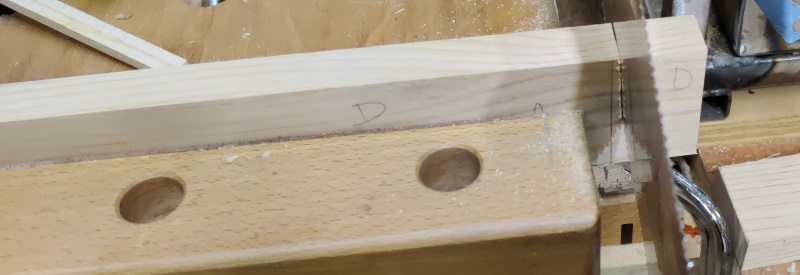
All of the back pieces that I'd planed flat and square were random lengths so the first job was do something about that. I trimmed them slightly over length using the Ryoba and my portable workbench:
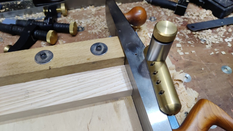
I then shot the ends square. This isn't strictly necessary as they're over length so the ends will get cut off later, but it makes one bit of marking up a bit easier later on (and I quite enjoy using the shooting board):
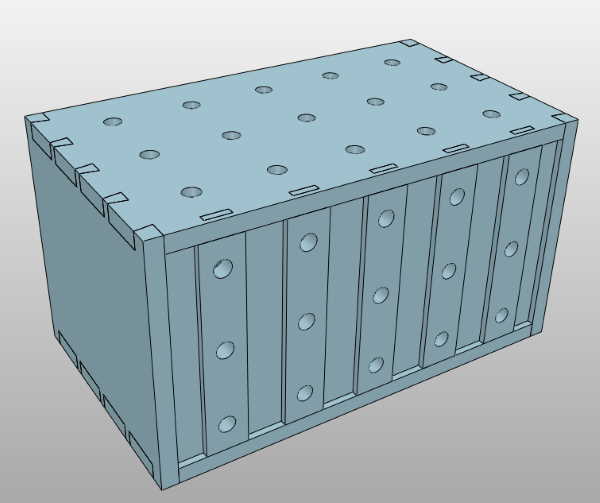
I then sketched out where the back pieces were going to go. This took a bit of thinking about. The CAD model has them spaced so that their centres are on a 96 mm pitch. When I drill the 20 mm holes in the centres of each back piece (as shown in the image at the top of the post) then it'll allow me to use various (mostly 3D printed) widgets that sit in 20 mm diameter, 96 mm pitch holes.
However, the chest isn't quite the same size as originally planned as I just made it the size that the wood came out. With the (admittedly quite small) changes, I worked out that it made more sense for the planks to be spread out on a 93 mm pitch. If I put the holes on a 96 mm pitch, the ones on the end uprights will be 9 mm from one edge of the upright and 21 mm from the other edge, which I guess might look odd, but I've got two options:
- Put up with it looking a bit odd.
- Put the holes on a 93 mm pitch instead: most of their use will probably be with simple (single hole) clamps rather than things with a fixed pitch.
Anyway, I've put that on the think-about-it-later pile.
The next choice was to decide how big the tenons are going to be. The cross-section of the uprights is 20 mm × 50 mm. Going with a width of about a third would imply 6.66 mm. I've got mortice chisels in 6 mm and 8 mm, but I'm making the conscious decision not to make the mortice exactly the same size as a mortice chisel (the one practice piece where everything worked really well was the one where I pared the mortice to width). To make things simple then, I rounded the third up and went with a width of 7 mm. Rather arbitrarily, I decided on 5 mm in from the end on the wider dimension.
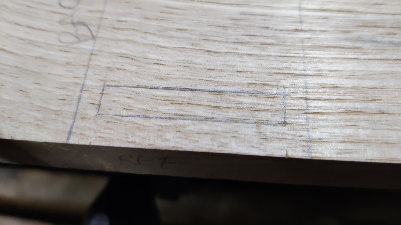
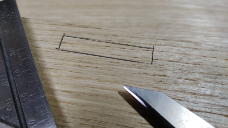
Having decided the spacing, I used a pencil to roughly mark out where everything was going to go and used a knife to put some notches in the edge of the board where the ends of the mortice will sit:
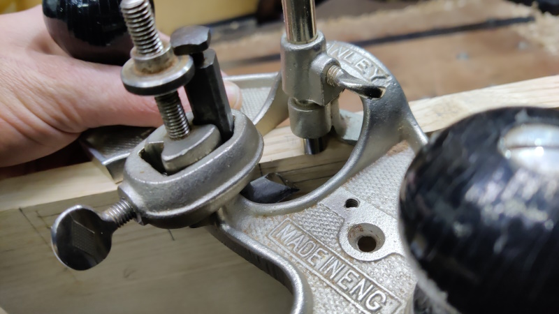
I then set my Stanley router plane to the dimension from the edge of the board to the nearest side of the mortice and used it as a makeshift marking gauge (on both sides of the both the top and the base board):
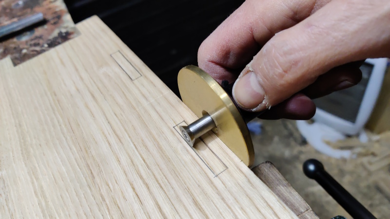
I used a normal marking gauge to cut a line for the far side of the mortice:
The notches I'd marked in the edge of the base board 5 mm in from where the edges of the uprights should go were then used to knife the ends of the mortices. I also used the notches to transfer the positions of the ends of the mortices from the base board to the top board so I could knife the ends of the mortices there as well.
An offcut from my test runs was also marked with the "router gauge":
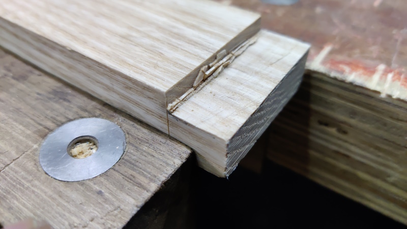
A square knife line was marked about 18 mm from the end of the offcut and then I sawed out the cheek and chiselled down the base line:
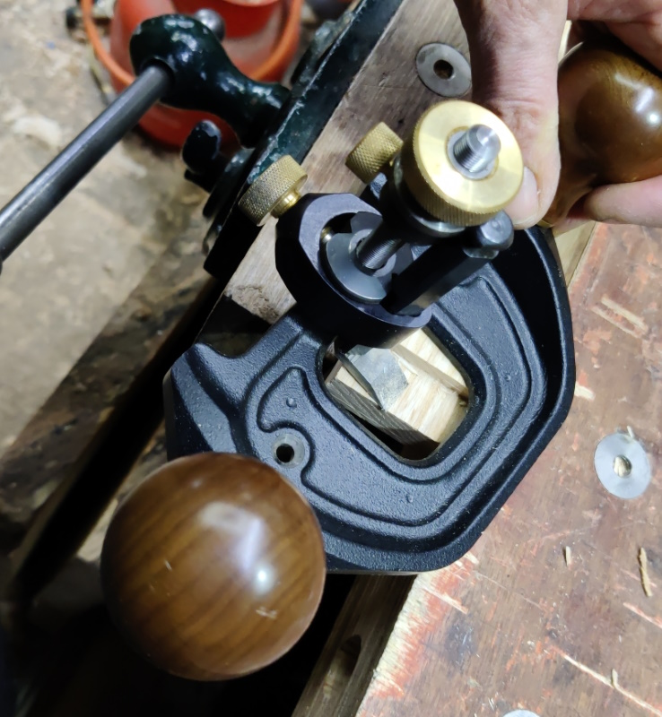
I then used my Veritas router plane to rough out most of the material until I was just above the gauge line, at which point I set the depth stop so I'd come down to the same point next time I do this:
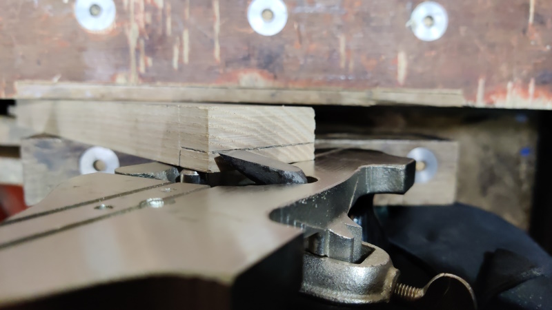
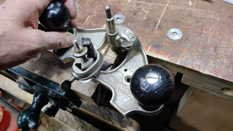
The Stanley router plane could then be used to take the final cuts at exactly the right depth:
Finally, I roughly sawed the end piece off about 50 mm (at a wild guess) from the base of the offcut's rebate.
Page 29 of 144
This website is free and ad-free, but costs me money to run. If you'd like to support this site, please consider making a small donation or sending me a message to let me know what you liked or found useful.

 Return to main project page