
Nodus Draw: Connectors and flowcharts
A connector is a line that stays attached to objects: move, resize or turn them and the connector follows. Connectors join the boxes of a flowchart, the blocks of a block diagram and the symbols of a circuit.
Drawing connectors
With the connector tool, drag from one object to another. Every object has anchor points: one at its centre and one in the middle of each side of its box. Symbols have their own too, at their terminals. Hovering over an object shows its anchor points as small diamonds; the one a press or a release would attach to is filled in.
- Drop an end on an object's centre and the connector chooses the side for itself: the side facing the other end. It chooses again whenever anything moves, so a box moved from below another to beside it is joined side to side instead. Objects with anchor points of their own (symbols) are joined at the nearest of those instead of their sides.
- Drop an end on a side (or one of a symbol's anchor points) to keep it there whatever moves.
- Hold Shift when letting go to keep an end at the object's centre.
- An end away from any object is free: it stays where it is put, snapping as drawing does.
Any number of connectors can start or end at the same anchor point: press on it and drag again for another one.
Choose sides automatically on the property bar (on unless you turn it off) does the same for the selected connectors, and for new ones. Where two objects are apart both across and down, its Z and L buttons choose between a connector that bends twice (across the bigger gap) and one that bends once (from the bottom of the upper object to the side of the lower).
Copies of connected objects (duplicated, or copied and pasted) keep their connectors if the connectors were copied with them. Deleting an object lets go of the connectors' ends there.
Straight or right-angled
The property bar chooses Straight connector or Right-angle connector (the default) for the selected connectors and new ones, and a corner radius to round a right-angled connector's bends.
A right-angled connector leaves each object straight out from its side, then runs across and up or down. It finds its own way:
- round objects in its way, keeping a little clear of them;
- beside other connectors rather than on top of them (crossing them where it must);
- along grid lines, while the grid is snapped to;
- with connectors from one place, splitting at one point (and those to one place meeting at one), as a flowchart's branches do.
Avoid connectors (on the right-click menu, and in the Properties docker's Object section) is on for every object except artistic text. Turn it off for an object that connectors should go straight through, such as a background box round a whole diagram.
To route a connector by hand, select it and drag one of its segments across with the shape tool (or the connector tool). It then keeps that route as things move, apart from the parts that meet its ends.
Changing a connector
- Its ends: select it and drag an end with the shape tool to another anchor point, or away from any object to let it go.
- Its style: like any line, with the palette and the Properties docker, including the arrowheads.
- The pick tool cannot drag a connector away from its objects: moving the objects moves it.
Labels
A connector can carry text, such as "Yes" and "No" from a decision.
- Right-click the connector and choose Add label (also on the Object menu), then type. The label starts just after the start of the connector, as "Yes" or "No" belongs next to the decision it comes from. To have new labels start halfway along instead, choose that in Tools › Options, New connector labels.
- Or select an artistic text and the connector together and choose Make text the connector's label.
A label moves with its connector. Drag it with the pick tool to put it somewhere else along the connector or beside it (it snaps, as other objects do); it keeps that place as the connector changes. Double-click it to change its text, and format it on the Properties docker's Character and Paragraph tabs.
Your own anchor points
Edit anchor points on the connector tool's property bar lets you add anchor points to any object:
- double-click the object to add one there (it snaps, so it can go exactly on a node);
- drag one to move it, or double-click it to delete it;
- click one to make it the main anchor: the point a symbol is held by when it is placed.
Anchor points you add are orange. They stretch and turn with the object. The centre and side anchor points cannot be removed.
Laying out a flowchart
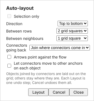
Tools › Auto-layout… arranges objects joined by connectors into rows on the grid: draw the boxes anywhere, join them up, and let it tidy them. Its window sits beside the drawing, so you can still see and change the drawing while it is open. It is greyed out until the page has a connector joining two objects.
- Selection only: lay out just the selected objects (connected objects not selected stay where they are).
- Direction: top to bottom, bottom to top, left to right or right to left.
- Between rows and Between neighbours: the gaps, in grid squares.
- Connectors going back (loops) go round the outside of the diagram and either join where connectors come in (into the top, for a diagram drawn top to bottom) or go into the side.
- Arrows point against the flow: for diagrams whose arrows point back up.
- Let connectors move to other anchors on each object: choose every connector's sides again. Off, the sides you chose are kept (unless they would make a connector double back).
Layout lays it out (one undo step each time) and leaves the window open to try other settings. Cancel undoes everything since the window was opened; Close keeps it.
How it arranges things:
- The way each connector goes is taken from its arrowhead, else from where it leaves and enters (bottom to top is downwards), else from where the objects are now.
- Objects go in rows, each below the last object leading to it, centred under the objects they come from where they can be, ordered to keep crossings down. Their centres go on grid lines (or their corners, for objects an odd number of squares across).
- Branches from one object leave by different sides, so they can be labelled.
- Text lying over an object moves with it, and labels move with their connectors. Objects not joined by connectors stay where they are, and the diagram moves aside rather than land on top of them.
- Separate diagrams are put side by side.
The Flowcharts library in the Symbols docker has the usual flowchart shapes, with anchor points where connectors should join them (see Symbols).
This website is free and ad-free, but costs me money to run. If you'd like to support this site, please consider making a small donation or sending me a message to let me know what you liked or found useful.